ELECTRICAL SYSTEM BASICS

Many emails over the years ask about electrical issues on their Honda’s, I thought that today I would try and add some information on here today to try and help you out a little.

The vintage bikes from the 1970’s, such as the HONDA CB550, have a simple electrical system consisting of approximately 40 components altogether making it possible for anyone with some basic skills and tools to build their own electrical harness.

Here are all of HONDA CB550’s electrical components:

HONDA-CB550-ELECTRICAL-COMPONENTS

Even though such a set-up may be as basic as they come, to be able to work on any electrical system and/or to make a new harness, a clear understanding of the essence of the electrical system is a must.  For me, anyway.  I am not very good at simply following instructions like purchase these components and then do this and that.

I like to know how things work.

So, here is my take on what is going on in any electrical system that is employed in any motorized vehicle.

The heart of the electrical system is the battery.  It powers everything.  But its power diminishes with use and so it must be replenished.  Exactly like the battery in your phone or the battery in any of your power tools. To recharge a battery, we need a source of electricity.  At home, it is easy.  Plug your phone into the wall outlet and it all happens automatically.  In a vehicle, a different source of “battery recharging power” is needed.

Enter the alternator.  The alternator (and all electricity generating devices that send power to your home) operates on the same principle as the one first, reportedly, employed by Michael Faraday nearly 200 years ago in the 1820’s when he observed that rotating a magnet inside a stationary coil of wires (or moving a “magnetized” coil in and out of a stationary coil to be precise) produces pulses of electricity.  The electrical current so induced alternates from + to – and for this reason it is called alternating current, and hence the name of the device that produces it.

The take-home lesson here is “a magnetic field rotating inside a coil induces electricity in the coil”.

In the HONDA CB550 engine, the “rotating magnet” is a combination of a rotor bolted to the crankshaft and a coil called a“field coil”.  The stationary coil is called a “stator coil”.

Neither the rotor nor the field coil are magnets themselves and so they cannot generate a magnetic field.  In order for the alternator to work, the field coil must be magnetized.  When electricity from the battery is sent to the field coil, a magnetic field is generated, which, through the rotor, is effectively rotating inside the stator coil.  This induces electricity.  (Like the old adage “you have to spend money to make money”. ) Exactly the same kind of electricity that Michael Faraday observed in his experiments mentioned above.  The electricity produced in this way is then used to recharge the battery.

Fair enough.  But, there is a problem.  An alternating current cannot charge a battery.   We need direct (a constant + and a constant –) current for that.  So, a way must be found to turn the alternating current (AC) into direct current (DC).

Enter the rectifier. The rectifier is essentially a bunch of diodes inside a housing.  Diodes are “filters”.  They allow only positive or negative charges to go through.  So, the AC goes into the rectifier, the positive charges go through one set of diodes, the negative charges go through another set of diodes and as a result DC comes out.  Job done.

But, now, there is another problem. What happens when the load on the battery is low (you are riding on the highway in daylight and the only electrical current consumed from the battery is going to the coils, which fire the spark plugs and that is not much at all)?  The DC current coming from the rectifier will charge the battery completely and if that current is uncontrolled, the battery will eventually become overcharged.  That’s not good.

Enter the voltage regulator.  This gizmo is placed between the battery and the field coil.  When the battery is low, the voltage regulator sends plenty of the battery’s electrical current to the filed coil, which produces a strong magnetic field and consequently a strong current is induced in the stator coil, which then goes through the rectifier into the battery.  When the battery is fully charged, the voltage regulator reduces the electrical current going to the field coil consequently reducing the current that goes to the battery.

Lets’ put this into numbers to make it a little clearer.  When the battery’s voltage is below 12V, the voltage regulator sends plenty of the battery’s power to the field coil.  When the battery’s voltage is around 14.5V or so, the voltage regulator sends very little power to the field coil and the induced electricity is essentially like you battery charger at home going into battery maintenance mode.

Here is a very basic schematics showing how the alternator, voltage regulator and rectifier are connected.

Basic-Electrical-Schematics


Looking at that, a seemingly obvious question is, “Why are there three yellow wires going from the alternator to the rectifier?” That is because the alternator is designed to produce three separate “pulses” of alternating current called phases.  All 3 go into the rectifier and all 3 are turned into DC.

The two thick black vertical lines to the right of the alternator represent a connector.

Now, let’s find out what these things actually look like.  Once the left side cover is removed, here is what we are going to see.

Electricla-box-with-rectifier-and-starter-relay-identified

The labeled connector in the photo is where the harness coming out of the engine is connected to (i.e. the connector mentioned above).  The three yellow wires coming out of that connector carry AC from the alternator.  That AC goes into the rectifier and DC comes out via the red (+) and green (-) wires.  The red wire is directly connected to the battery.

Taking a look at the back of the electrical components box, we can see the voltage regulator.


Voltage-regulator-identified cb550f

Power to it comes down the black wire once the ignition is switched on.  Power to the field coil is sent via the white wire.  The green is ground.

That’s all there is to it.

Let’s recap: When the ignition switch is turned on, power from the battery arrives at the ignition coils and the voltage regulator.  The ignition coils are energized.  The field coil is magnetized. Kick the kick start and the engine fires, the alternator starts producing electricity (AC), the rectifier turns it into DC, which goes to charge the battery.  Once the battery is fully charged, the voltage regulator makes the alternator produce less electricity so the battery is always optimally charged.  Cycle complete.  And we are back to where we started when we said, “The battery is the heart of the electrical system.  It powers everything”.

What this teaches us is that all that is needed for the machine to run is: ignition switch, battery, voltage regulator, alternator, rectifier, ignition coils and points.  None of these components can be eliminated without negative impact on performance.

Everything else is, more or less, optional.  A fuse or fuses are a prudent addition.  A headlight, tail light(s), brake light(s) and turn signals (as well as their associated switches and relay) may be required by law. If the electric start is to be retained, then the starter relay and a start switch will be needed.

And then come the “conveniences and luxuries” such as neutral gear switch, neutral gear light, oil pressure sensor and associated light, etc.

With this in mind, a brand new harness can easily be put together.  If the original components are not available or desired, many quality aftermarket parts can be used.  These days the rectifier and voltage regulator come in a single unit, which is the preferred solution for café racer and custom builders since it saves a little bit of space.

Thanks to: Kyril of Black Square Motorcycles, very informative.

Below are some Schematics I have added to help you on your Honda CB750 Models. First is a KO-K1-K2

CB750k1

Then a CB750 Automatic Schematic.

CB750auto

Below a CB750F 1977-1978 Diagram.

Honda Cb750 Wiring Diagram Honda Ca95 Wiring Diagram • Wiring Articles and Images - Automotive Wiring Diagram
Honda Cb750 Wiring Diagram Honda Ca95 Wiring Diagram • Wiring Articles and Images – Automotive Wiring Diagram

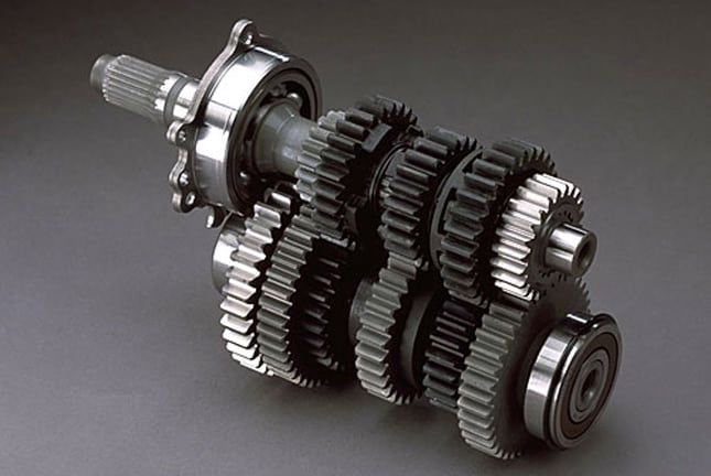
Constant Mesh Gearbox- Great explanation for you.

Happy Hump day folks.

Sometimes, people ask me all sorts of question on the Motorcycles I work on, now, here is a superb explanation from Hot Bike, that clearly informs you as to the purpose of a Constant mesh Sequential gearbox and how they function.

So there you go, today you may of picked up a little more understanding of a close ratio gearbox and hope it cheered your day up?

constant

Thanks for watching and now you know what the real term “Shifting gears” means.

Tech Tip, how to Undo Tight Bolt by Hand.

Hey there, happy Friday to you all from an actually Rainy Southern California, something that is quite rare these days but we need to rain so I dont mind the H20 coming down in buckets right now.

So- As to make the most of this wet day I had a few things that I needed to do and one of them was to take an old Sprocket and chain Guard off a CB750K rear Hub.


Now- many people ask me for a few tips and I shall be answering a few of these questions over the next few days in blogs etc, but today I had to remove these parts of the Rear wheel Hub and the nuts on here were factory tightened.

Now, if you have no air tools and the Nuts on the hub or anything that you need to remove are tighter than a Scotsman Wallet, then, here is a little trick I do when I need to get something that tight undone and using minimum tools.

I use my regular socket and wrench and then I grab an old Fork tube and slip that over the wrench handle.

This Leverage now produces close to 2 Tons of pressure and is known as a Fulcrum.

This has worked for me for over 40 years now, my old man taught me and you may know an easier way if you don’t have power tools, but for me it is so easy to do and wanted to share today.
This works on ANYTHING, give it a go, you will surprise yourself.

Thanks for watching and have a great weekend.

Checker Tape – HOW TO APPLY AT HOME

Well, I thought that it would help if I did a blog, and then later I would add this to the tips page, of how to apply the checker tape etc.

I was the first to start all this many years ago, actually 13 years ago next week and here is how apply my Checker kits.

This is quite easy to be honest, all you need is a clean area, soapy water, in one of the spray bottles, a credit card and a micro fiber cloth.

What I do is clean the area that is going to have the checker tape, and how I do that is use soapy water in a spray bottle that you can buy anywhere.

Now just fine mist that all over the area you are going to apply too, this will get rid of all the dust and static to be honest, then, I simply puff the back of the tape with the water too and then I apply the tape.

Now, you really do need a straight eye for this, so make sure you have a center point, else you could get as crooked as a warped walking stick if you are not careful.

I lay the checker tape in place and then, by using a credit card, I wrap the card in a microfiber cloth or even a tee shirt will do, I then apply even pressure on the tape and draw or pull down quite firmly.

This eliminates all the water and of course, any water bubbles, and smooths everything out.

Now, if you are not happy, you can simply move the checker whilst it is wet, as the soap will help that slide, or you can peel it off, water again and apply and then smooth out, once you are happy, just smooth until the water is out and check the edges for any bumps and hidden water droplets that are hiding.

Now, this is the same process for any thing that you are going to apply to, above was a Rocket 6 seat base that I was getting ready, and now I am going to start on one of my gas tanks.

This has been painted and scuffed, so my decal can adhere to the paint and then after the tape is on and dried, I pin line the outside of the checker to finish the look off.

Did anyone catch the wardrobe change???

Also, if you are still a little stuck, then check my video out below, as this may help?

Identifying CB750 Frame Year & Engine Number

Many people ask me about how to tell what year their frame is or what year their motor is, so I thought I would add an identification listing of all CB750 S.O.H.C. models.

With Model, Frame and engine year.

Hope this helps you… as it sure does help me out at times.


Honda CB 750 Identification Numbers

K SERIES MODELS

Model Name              Frame Number                Engine Number

CB 750 K-0                 CB750-1000001                    CB750E-1000001

CB750 K-1                   CB750-104465                      CB750E-1044806

CB750 K-2                   CB750-2000001                   CB750E-2000001

CB750 K-3                   CB750-2200001                    CB750E-2200001

CB750 K-4                   CB750-2300001                    CB750E-2300001

CB750 K-5                   CB750-2500001                    CB750E-2372115

CB750 K’76                  CB750-2540001                   CB750E-2428762

CB750 K’77                  CB750-2700009                   CB750E-2700001

CB750 K’78                  CB750-2800001                   CB750E-3000001


SUPERSPORTS F SERIES MODELS

Model Name               Frame Number                Engine Number

CB750F (1975)           CB750F-1000002                  CB750FE-2500004

CB750 F’76                  CB750F-2000003                 CB750FE-2515094

CB750 F’77                  CB750F-2100011                  CB750FE-2600004

CB750 F’78                  CB750F-2200001                  CB750FE-3100001


HONDAMATICS

Model Name               Frame Number                 Engine Number

CB750 A’76                 CB750A-7000001                  CB750AE-7000001

CB750 A’77                 CB750A-7100001                  CB750AE-7100001

CB750 A’78                 CB750A-7200001                  CB750AE-7200001

Saving time removing bolts

Well, if you are anything like me, you want to try and save time where ever you can on a machine, especially if the weather is steaming hot or bloody cold.

What I do when I remove bolts etc, is quite simple and many of you may already do this, but go to the local hardware store and but a 3/8″ drive socket adapter for an cordless drill.

That way these are easy to undo and fast, as well and fitting new bolts and will not only save you time, it will stop your arm aching using a screw driver.

Hop Up Tricks – The Formula

First off get rid of that big plastic air box with the rubber intake runners and put on a set of air filters Pods. This does two thing right off the bat, cuts off 10 lbs of weight and lets the motor pull in more, cooler air. [Cooler + More = Horsepower] The reason this is better is the air behind the engine there is a lot cooler than the air being sucked in from under the seat above the exhaust pipes. Also you get the swirling action going down the hole from the individual air filters for each carburetor which intern cools the air charge even more, remember the formula [Cooler + More= Horsepower]

How To Mount Your Own Tire

Note We found this tip on a non-US website and translated it. So if there are a few word goofs it was because of the translation. Although we feel all tires should be mounted by a professional. Some of you bone heads are going to try it on your own. So at least this offers you some direction. But remember it’s on you!

Because any project that involves just you will save you money. If you buy mail order tires at a bargain price, you’ll have to find the nearest tire-fitting service, and nine times out of 10 you’ll be charged the earth to have another supplier’s tires fitted to your rims. It can also save a lot of time and grief carting loose wheels somewhere, then having to wait for them to be done, or pick them up later.

 Don’t I need special kit?

As a rule of thumb, bikes with small rim sizes – say up to three-inch front and four-inch rear – only need muscle power to ‘break the beading’. That is, to break the airtight seal between the tire and the wheel’s rim wall. Larger rims obviously run with bigger, wider tires, and ideally a hydraulic bead-breaking machine should be used for this job – not the sort of device you’d find in every biker’s garage. But, as you’ll read here, there are cheaper ways to get round this.

What is required is a set of tire levers that are suitable for the job and a tire valve key (available from any car/bike spares shop) or pronged-type valve cap. Bicycle tyre levers aren’t man enough for the job. A half-decent set can be bought from a mail order firm for about £10 a pair – get friends to chip in, as levers are always in demand. Hard plastic rim protectors (£5 a pair) are a good investment too, as they prevent scratching the paint and the aluminum beneath.

As for your own ability, muscle power isn’t everything. Like most things in life, first-time anticipation is more worrying than the event itself. Practice makes perfect, so we respectfully suggest practicing on something like a Honda C50/70/90 wheel first.

Tubed or tubeless?

Bikes with wire-spoked wheels (generally trail bikes and small commuter bikes) more often than not run with tubes – as wire-spoked rims aren’t airtight unless the spokes are mounted outside of the rim (as on some BMW GS models). More bikes today have cast or forged aluminum wheels that run tubeless-type tires and while the fitting of these and tubed tires is similar, the addition of a tube makes fitting trickier – more care is needed as ‘nipping’ a tube with a tire lever and putting a hole in it is easily done.

1. Deflate the tire by depressing the valve before removing it fully with a valve key – high pressure in the tire can cause the valve to fly out and disappear. If a tube is fitted, loosen the valve’s securing nut but do not remove, just unwind it to the top of the valve, so the tube can move away from the rim and won’t be trapped by a tire lever.

2. Several methods can be used to ‘break’ the rim/tire seal. On small-sized tires, the heel of a boot placed on the tire, as close to the rim as possible, and forced downwards to push the tire into the rim’s well (center) while pulling up on a spoke will suffice. Turn wheel over and repeat. Put down carpet or cardboard to prevent damage to rim or disc.

3. Breaking the beading in a vice is a cheap and safer alternative, and more suitable for larger tires. With the jaws open to the max, place the wheel in the vice so the top of the jaws are within 5mm of the rim. Holding the wheel in place, slowly and carefully (to avoid marking the rim) tighten the vice until the seal is broken. Repeat for the other side.

4. For around £60, a purpose-made bead breaker is the safest and easiest way to break any tyre rim seal without damage. They come in a variety of styles, ranging from elaborate scissor-like mechanisms to over-sized G-clamps. What may seem an unnecessary expense can quickly be recouped from friends, or even at trackdays.

5. Place the wheel flat on the floor, preferably on a mat to avoid any damage. With both hands either side of the tire, squeeze hard to help the tire drop in to the ‘well’ (middle) of the wheel. This makes fitting a tire lever and removal of the tire a lot easier – you won’t be trying to stretch the tire off the rim.

6. With one tire lever, carefully insert the tip between rim and tire, push it away from you and fit a rim protector. Lift the lever so the lip of the tire lifts over the rim. Hold this lever down with your knee and repeat with another lever 3-4 inches further along…

7. …Remove the first lever and lift the tire lip another 3-4ins further along from the second lever. Work the levers and protectors round the tire until its lip is clear of the rim. Stand the wheel up and feed a lever from the opposite side under the tire and through to the rim (with protector) and lift the lever to push the tire off the rim.

8. Take the new tire and paint some lubricant on to the outer lips of both sides of the tyre to aid fitting – especially when blowing the tire up – so it butts on to the rim easily. Professional tire services use ‘tire soap’. If this is not available, use a thick, soapy solution of liquid hand soap and water. Swarfega can be used if applied liberally.

9. Ensure the tire’s rotation of direction arrow (marked on sidewall) matches with the wheel’s (cast on rim). Slide, pull and push one side of the tire on to the rim by placing the rim on to the lower part of the tire, holding it in place with a foot and pushing the rim into the tire from the bottom – lubricant, levers and protectors are a must.

10. With the wheel flat on the floor and the open side of the tire facing up, carefully feed in the tube (if fitted). Blow it up slightly to assume its circular shape so it doesn’t get trapped between tire and rim. Don’t screw down the valve-securing nut yet as you need some slack when fitting the last part of the tire on the rim.

11. Starting at 180° from the valve, carefully start to lift the tire lip over and on to the rim, alternating from left to right, so the last part of the lip to go in to the rim is at the valve. Try to keep the fitted lip (underside) in the rim’s well to make fitting easier. When lifting the last part over, push the tube valve back into the rim to prevent it being trapped.

12. Inflating the tire requires a compressor. Garage forecourt pumps are fine. Keep inflating the tire until the sidewalls seat on the rim (molded lines on the tire will be visible all the way round, near the rim, and at an even distance). Finally, reset the pressure. Don’t ride until the wheel has been balanced.

My Throttle Cables Sticks.

Well, i get this question all the time.

You can make shorter cables and that’s not cheap these days. the 750 Honda does not have solder removable nipples, so, what I do if I use Clubman bars, is I simply re-route them.

I fit the cables on the throttle and then they face out and I route them to the front of the bike, I thread them in front of the forks and then above the lower tree.

I make sure that the cables fit nice on the left side of the triple tree by the brake switch, then hug to the frame, under the coils and onto the carbs. I fit the lower cable forst and the top last, just easier to handle.

Unless you have hands of a four year old.

You have some adjustment on the cables ends by the carb too, check that as well, as you will be surprised as to how much you can get the cables to be really responsive by adjusting the 10mm nuts there.

I also add a dab of Lithium grease to the slide rods too.