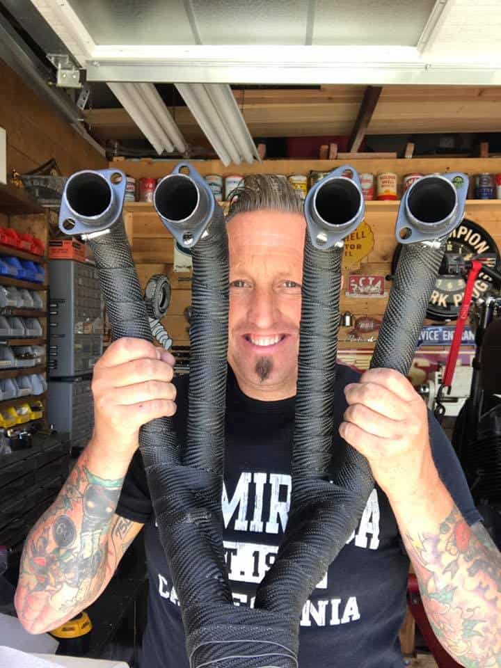
New beginnings for 2022, Looking forward to it.

The New Year is here, still a crazy world out there and I am not taking any risks to get ill again, I got all my shots, I then caught Covid and then at Christmas got a cold almost as bad as the New Omicron, what a shit start to the year for sure, but- I have got the cold just about beat, still coughing like a badly tuned motor, but I am on the road once more.

For over 20 years I have rented a building for what I do, we all throw away good money on rent and the Landlord is the only person that makes anything out of that, but- this year is all different, about 7 months ago we put in plans for a barn to be built on the 1 acre we have here in La Habra heights. We had to jump through the many hoops and have many inspections, but at last we are now making some great progress.

Once the Concrete slab was laid and left to cure for a whole month, we started to get the Barn ready to go together on Wednesday, the sun was out and the rain storm we had for a week before had gone, this is a really excited time for Carpys Garage and wanted to share some of the build with you.

A great Company that makes steel Barns for many years was the choice that we went for, robust and affordable, a steel skeleton is constructed and bolted with high grade bolts to the Concrete floor, this is a sturdy set up and am glad that we went this route.

I have no idea how I am going to decorate as yet, that all takes time and of course money, but the main thing is to get the workshop put together and then see what I can do to make it my own and have fun creating what I do from the comfort of home. And not a drive to work either.


This will indeed be the perfect place for inspiration and dont have to worry about parking, or the street sweeper etc or the Land lord coming by to increase their rent, this is a bitchin set up and super stoked to be doing this.

It is the perfect size for me and although will take a little time to dial in, it will be such a relief to jump out of bed and stroll up the yard to the Barn and begin to make parts or create builds to offer the Customers all over the globe.

I wanted a Red Old style Color Barn as the area we are in has many Ranches etc. And we thought this color will fit right in, hope to find an old Cart Wheel later to add to the side and of course old industrial Lights to mount outside, along with a Cow or Bull skull with Horns.

Lots t do but making great headway and will be a fun project as we go along, some might not understand the importance of your own workshop, but those who do, will really get how stoked I am to be in this situation.


Eventually I shall decide on a cool Barn door, as I don’t want just a regular roll up, they are noisy too, so I am looking into a few styles with Jennifer to see what would look good on the front.

It is also a nice wide opening, so I can get my bikes and Hot Rod in there with no issues, the run off is super good if we do get any more of the wet stuff.

Just wanted to share the news with all you lot, I know that a lot of you will be stoked for me and I look forward to making brand new parts here from the countryside of ideas.

Its Bulldog approved now and she will enjoy hanging out again in the garage as she was in many of my shops and loved hanging around in the workshop all day.

So, thanks for reading my little Blog and I will show more of when I have got other stuff finished in the Barn, but good things are happening and many thanks for sticking by me.


Thought I would show the New Little CB350RS HONDA that’s out and about, very Nostalgic looking, what do you think?

ELECTRICAL SYSTEM BASICS

Many emails over the years ask about electrical issues on their Honda’s, I thought that today I would try and add some information on here today to try and help you out a little.

The vintage bikes from the 1970’s, such as the HONDA CB550, have a simple electrical system consisting of approximately 40 components altogether making it possible for anyone with some basic skills and tools to build their own electrical harness.

Here are all of HONDA CB550’s electrical components:

HONDA-CB550-ELECTRICAL-COMPONENTS

Even though such a set-up may be as basic as they come, to be able to work on any electrical system and/or to make a new harness, a clear understanding of the essence of the electrical system is a must.  For me, anyway.  I am not very good at simply following instructions like purchase these components and then do this and that.

I like to know how things work.

So, here is my take on what is going on in any electrical system that is employed in any motorized vehicle.

The heart of the electrical system is the battery.  It powers everything.  But its power diminishes with use and so it must be replenished.  Exactly like the battery in your phone or the battery in any of your power tools. To recharge a battery, we need a source of electricity.  At home, it is easy.  Plug your phone into the wall outlet and it all happens automatically.  In a vehicle, a different source of “battery recharging power” is needed.

Enter the alternator.  The alternator (and all electricity generating devices that send power to your home) operates on the same principle as the one first, reportedly, employed by Michael Faraday nearly 200 years ago in the 1820’s when he observed that rotating a magnet inside a stationary coil of wires (or moving a “magnetized” coil in and out of a stationary coil to be precise) produces pulses of electricity.  The electrical current so induced alternates from + to – and for this reason it is called alternating current, and hence the name of the device that produces it.

The take-home lesson here is “a magnetic field rotating inside a coil induces electricity in the coil”.

In the HONDA CB550 engine, the “rotating magnet” is a combination of a rotor bolted to the crankshaft and a coil called a“field coil”.  The stationary coil is called a “stator coil”.

Neither the rotor nor the field coil are magnets themselves and so they cannot generate a magnetic field.  In order for the alternator to work, the field coil must be magnetized.  When electricity from the battery is sent to the field coil, a magnetic field is generated, which, through the rotor, is effectively rotating inside the stator coil.  This induces electricity.  (Like the old adage “you have to spend money to make money”. ) Exactly the same kind of electricity that Michael Faraday observed in his experiments mentioned above.  The electricity produced in this way is then used to recharge the battery.

Fair enough.  But, there is a problem.  An alternating current cannot charge a battery.   We need direct (a constant + and a constant –) current for that.  So, a way must be found to turn the alternating current (AC) into direct current (DC).

Enter the rectifier. The rectifier is essentially a bunch of diodes inside a housing.  Diodes are “filters”.  They allow only positive or negative charges to go through.  So, the AC goes into the rectifier, the positive charges go through one set of diodes, the negative charges go through another set of diodes and as a result DC comes out.  Job done.

But, now, there is another problem. What happens when the load on the battery is low (you are riding on the highway in daylight and the only electrical current consumed from the battery is going to the coils, which fire the spark plugs and that is not much at all)?  The DC current coming from the rectifier will charge the battery completely and if that current is uncontrolled, the battery will eventually become overcharged.  That’s not good.

Enter the voltage regulator.  This gizmo is placed between the battery and the field coil.  When the battery is low, the voltage regulator sends plenty of the battery’s electrical current to the filed coil, which produces a strong magnetic field and consequently a strong current is induced in the stator coil, which then goes through the rectifier into the battery.  When the battery is fully charged, the voltage regulator reduces the electrical current going to the field coil consequently reducing the current that goes to the battery.

Lets’ put this into numbers to make it a little clearer.  When the battery’s voltage is below 12V, the voltage regulator sends plenty of the battery’s power to the field coil.  When the battery’s voltage is around 14.5V or so, the voltage regulator sends very little power to the field coil and the induced electricity is essentially like you battery charger at home going into battery maintenance mode.

Here is a very basic schematics showing how the alternator, voltage regulator and rectifier are connected.

Basic-Electrical-Schematics


Looking at that, a seemingly obvious question is, “Why are there three yellow wires going from the alternator to the rectifier?” That is because the alternator is designed to produce three separate “pulses” of alternating current called phases.  All 3 go into the rectifier and all 3 are turned into DC.

The two thick black vertical lines to the right of the alternator represent a connector.

Now, let’s find out what these things actually look like.  Once the left side cover is removed, here is what we are going to see.

Electricla-box-with-rectifier-and-starter-relay-identified

The labeled connector in the photo is where the harness coming out of the engine is connected to (i.e. the connector mentioned above).  The three yellow wires coming out of that connector carry AC from the alternator.  That AC goes into the rectifier and DC comes out via the red (+) and green (-) wires.  The red wire is directly connected to the battery.

Taking a look at the back of the electrical components box, we can see the voltage regulator.


Voltage-regulator-identified cb550f

Power to it comes down the black wire once the ignition is switched on.  Power to the field coil is sent via the white wire.  The green is ground.

That’s all there is to it.

Let’s recap: When the ignition switch is turned on, power from the battery arrives at the ignition coils and the voltage regulator.  The ignition coils are energized.  The field coil is magnetized. Kick the kick start and the engine fires, the alternator starts producing electricity (AC), the rectifier turns it into DC, which goes to charge the battery.  Once the battery is fully charged, the voltage regulator makes the alternator produce less electricity so the battery is always optimally charged.  Cycle complete.  And we are back to where we started when we said, “The battery is the heart of the electrical system.  It powers everything”.

What this teaches us is that all that is needed for the machine to run is: ignition switch, battery, voltage regulator, alternator, rectifier, ignition coils and points.  None of these components can be eliminated without negative impact on performance.

Everything else is, more or less, optional.  A fuse or fuses are a prudent addition.  A headlight, tail light(s), brake light(s) and turn signals (as well as their associated switches and relay) may be required by law. If the electric start is to be retained, then the starter relay and a start switch will be needed.

And then come the “conveniences and luxuries” such as neutral gear switch, neutral gear light, oil pressure sensor and associated light, etc.

With this in mind, a brand new harness can easily be put together.  If the original components are not available or desired, many quality aftermarket parts can be used.  These days the rectifier and voltage regulator come in a single unit, which is the preferred solution for café racer and custom builders since it saves a little bit of space.

Thanks to: Kyril of Black Square Motorcycles, very informative.

Below are some Schematics I have added to help you on your Honda CB750 Models. First is a KO-K1-K2

CB750k1

Then a CB750 Automatic Schematic.

CB750auto

Below a CB750F 1977-1978 Diagram.

Honda Cb750 Wiring Diagram Honda Ca95 Wiring Diagram • Wiring Articles and Images - Automotive Wiring Diagram
Honda Cb750 Wiring Diagram Honda Ca95 Wiring Diagram • Wiring Articles and Images – Automotive Wiring Diagram

Vintage Hot Rod Turn Signals (wiring diagrams, etc. . .)

Not sure if you have run into this problem, but we’ve put a bunch of those old turn signals on a few of the cars we’ve built over the years (Signal Stat, Yankee, etc. . .) Every time I pick one up it never fails that I’ll spend an hour or so with the multi-meter trying to figure out how to wire it up.

I came across these wiring diagrams on “Hot Rod Confidential” the other day and figured I’d put them here so the next time I need to figure it out I’ll know right where to look. . . and if you need it too, now you’ll know where to look: